NLMS - Dutch ModelRailroad -
www.nlms.info
Welcome at the Digital section,
both Motorola and DCC.
I surprised myself in 2004 by changing to digital command control to operate
my layout. At eBay I was able to buy a MRC commander 2000 for a nice little
price. However compared to other dcc systems the capabilities with the commander
2000 are limited. But experimenting with this MRC dcc system and two dcc
equipped locomotives, changed my mind quickly.
The biggest part of my layout is going to be digital controlled. After
research on the internet as to what all the possibilities are, and still owning
a few old computers I decided to use a software system that allows a computer to
generate the required digital signals. The software I have running is available
as a free download, thanks to there designers, on the internet, at the following
websites: MRDirect and
Koploper. The websites and software is in
the Dutch language, but this kind of software should be available in other
languages, like English and German.
Description of the software will soon be available at the software menu
selection.
My layout is operated with two computers, and the system is almost like a
Intelibox. It handles both the Marklin Motorola format and the NMRA DCC format.
These different formats can be interchanged simultaneously. My track switches
decoders and signals decoders are from the Motorola system and the train
decoders are from the DCC format. (MRC and Lenz) Track occupancy works with the
S88 system, all self-made except for the DCC locomotive decoders.
I have made a few circuit boards and each one with it's own function. I found
the schematics in books and on the internet. Some are a combination of circuits
and may have small modifications. The signal decoders are modified track switch
decoders, and I have the schematic from Mr.
A. de Heer.
Click on his name for his website, however it is in Dutch. I have also found a
lot of information on the website from Mr.
R. Evers.
Click his name to visit his website, also in Dutch. I am thankful to these two
persons for the help in making these decoders.
I have painted the circuit boards in various colors for ease of
identification.
I had plenty of spray cans of paint left over anyway. So are the switch decoders
red, high power switch decoders yellow, signal decoders orange, and the S88
feedback circuits blue. And finally the occupancy detectors are painted green.
Click on the photo for a picture in higher resolution and size, if available.
|
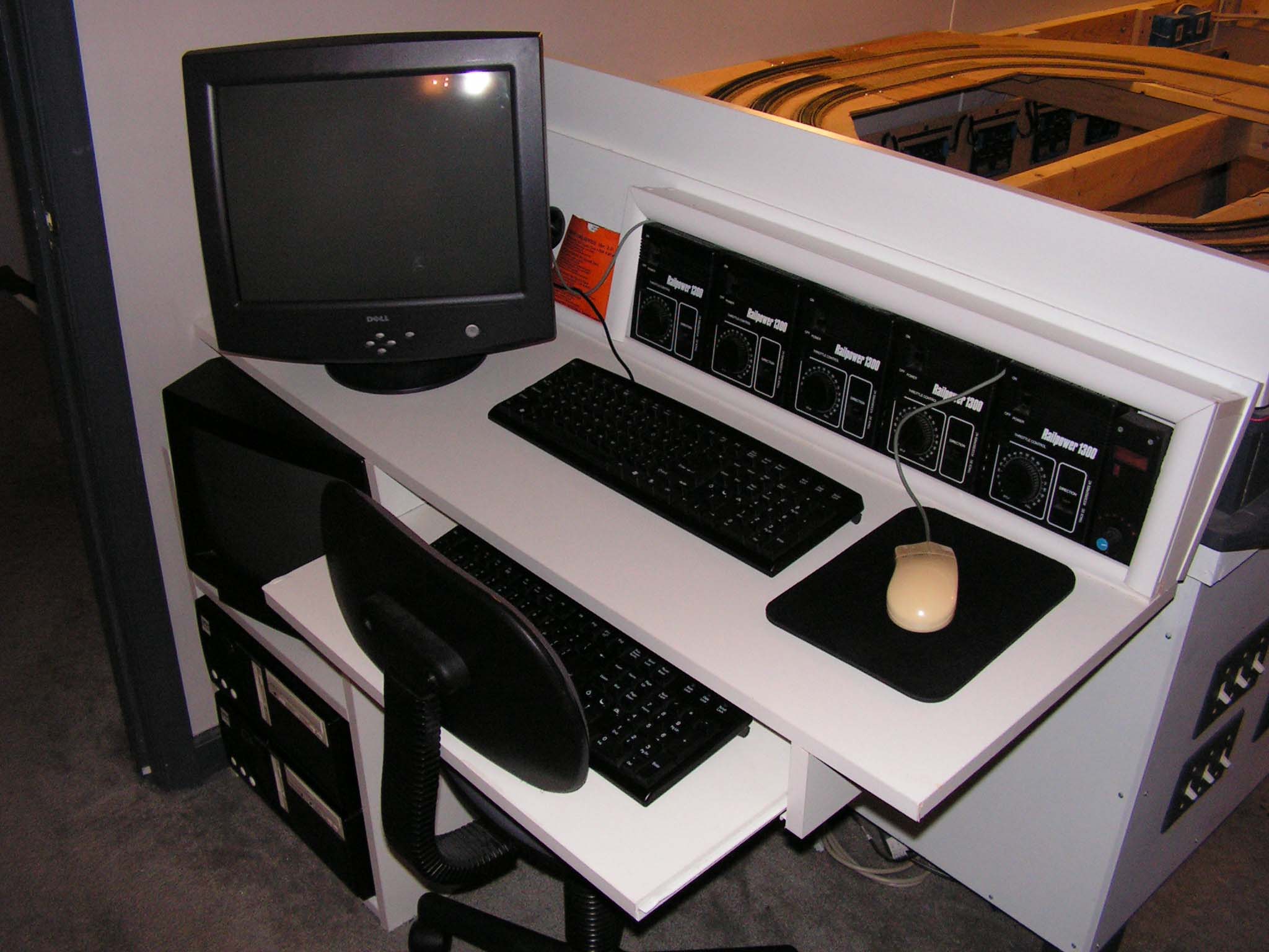
The "control center"
The first computer controls the decoders, both train and track switch
/ signals. He is also responsible for the track occupancy. This computer
runs MRDirect.
The second computer controls the first computer, allowing for a full
automatic timetable operation as well as manual controlled by mouse and
keyboard operation of the layout. This computer runs on Koploper. |
|

At the left bottom the two computers in charge of the digital part of
the layout.
|
|
|
|
|
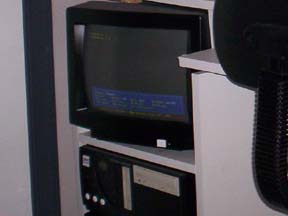
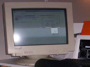
Here the monitor from the first computer with MRDirect. |
|
Here the monitor from the second computer with Koploper. |
|
|
|
|
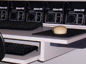
Five brand new transformers, purchased before I converted to digital
control, are still being used on the layout. |
|
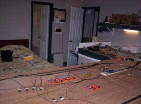
This is a test layout to get to know the software Koploper. With
this layout I also tested the various circuit boards I made, as well as
the hard and software on the computer it self. |
|
|
|
It takes a little while to learn to program the software, but after a
little while it all works perfect. This test layout is already
disassembled and in it's place is the staging yard build. Not yet
programmed in the computer though. |
|
|
|
|
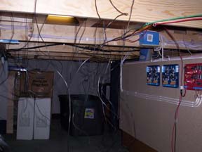
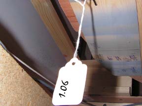
Here we take look underneath the staging yard with 10
tracks. The wires hanging down are for the track occupancy, which has to
be hooked up still. |
|
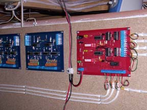
The red circuit board is a double track switch decoder witch
operates the 8 track switches in the staging yard.
|
|
|
|
|
 |
|
 |
|
|
|
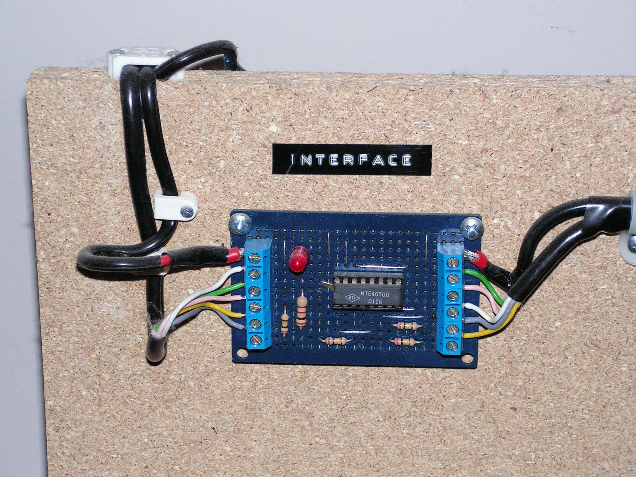
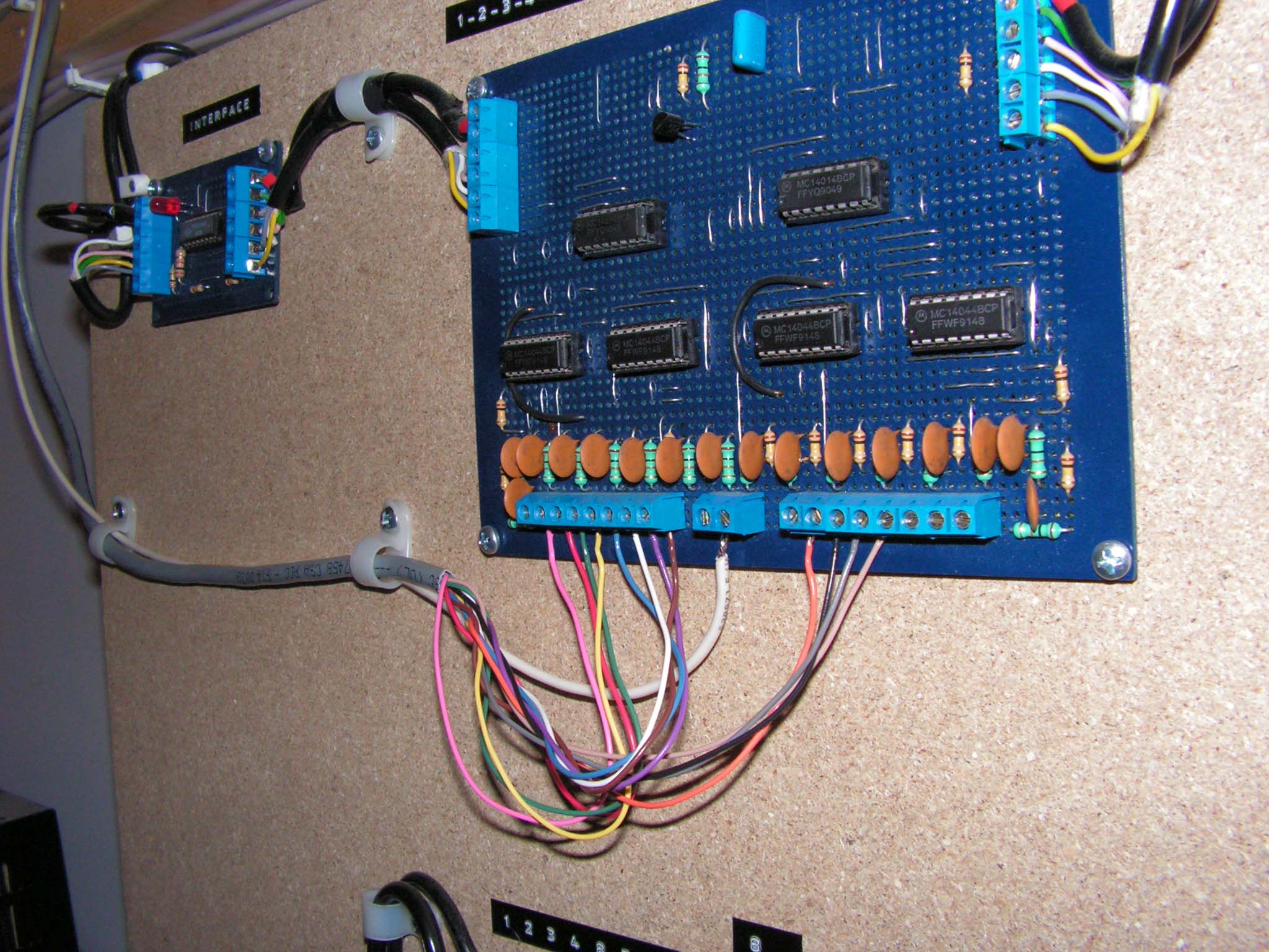
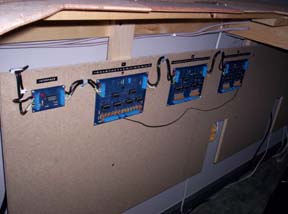
Connected like a chain, the S88 circuits. The small circuit board in
front is a interface. The S88's are used for track occupancy. At this
time I have 9 circuit boards with 16 detectors each. This is a total of
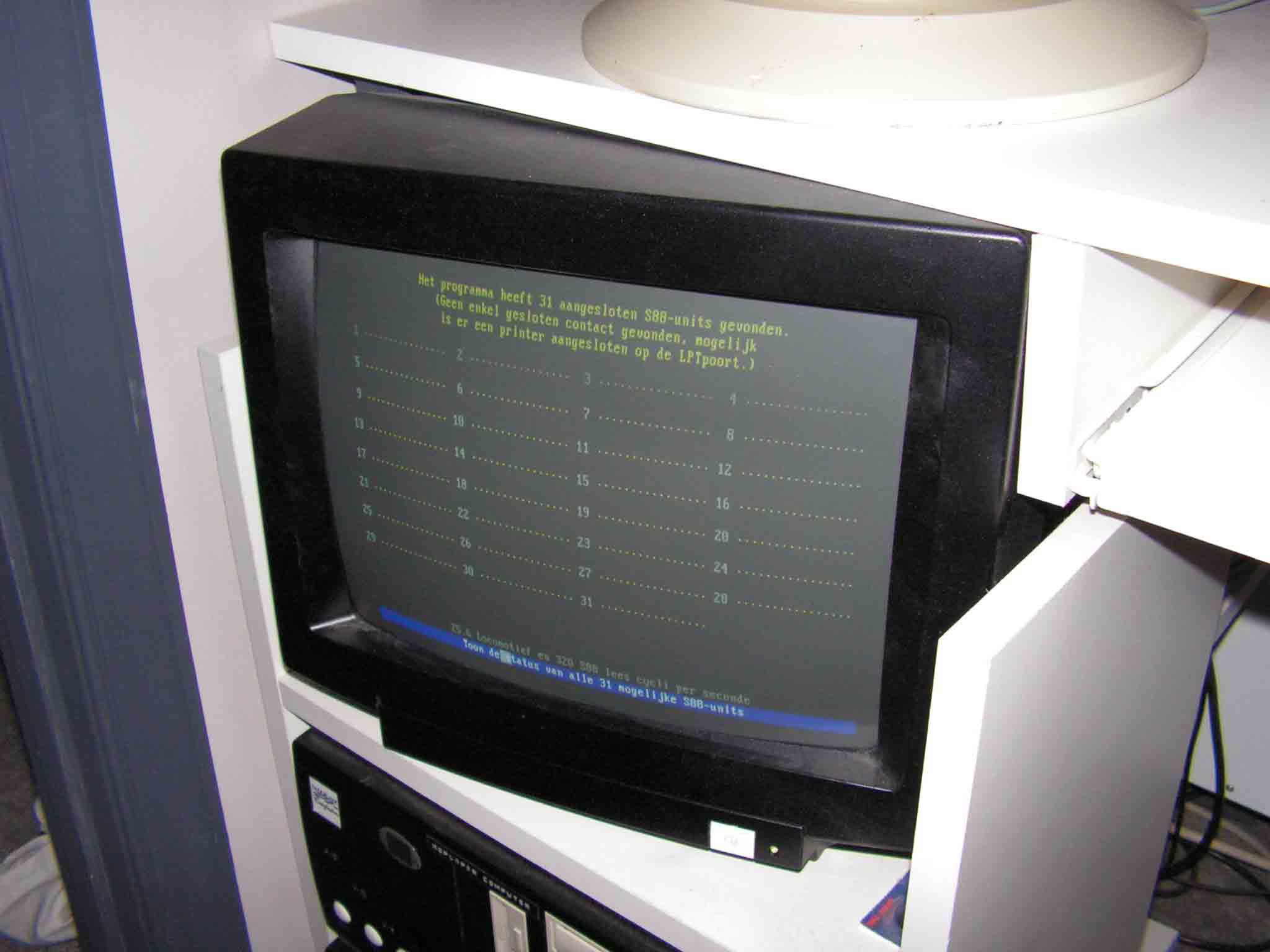
144 detectors. The computer can read a maximum of 31 S88 circuit boards,
which totals 496 detectors! |
|
|
|
|
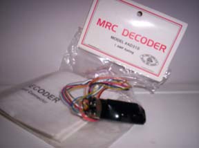
MRC decoders as used on my layout, I got them cheap from a
co-worker. |
|
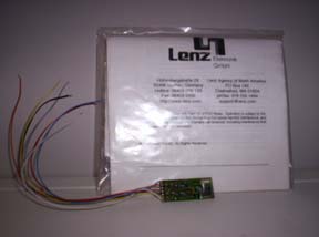
I also have two Lenz decoders with functions. |
|
|
|
|
|
Ready to be put in service: six freshly soldered S88
circuit board. |
|
|
|
|

The result of a few months soldering circuit boards
in the evening. |
|
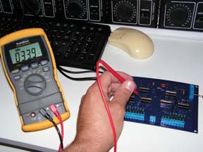
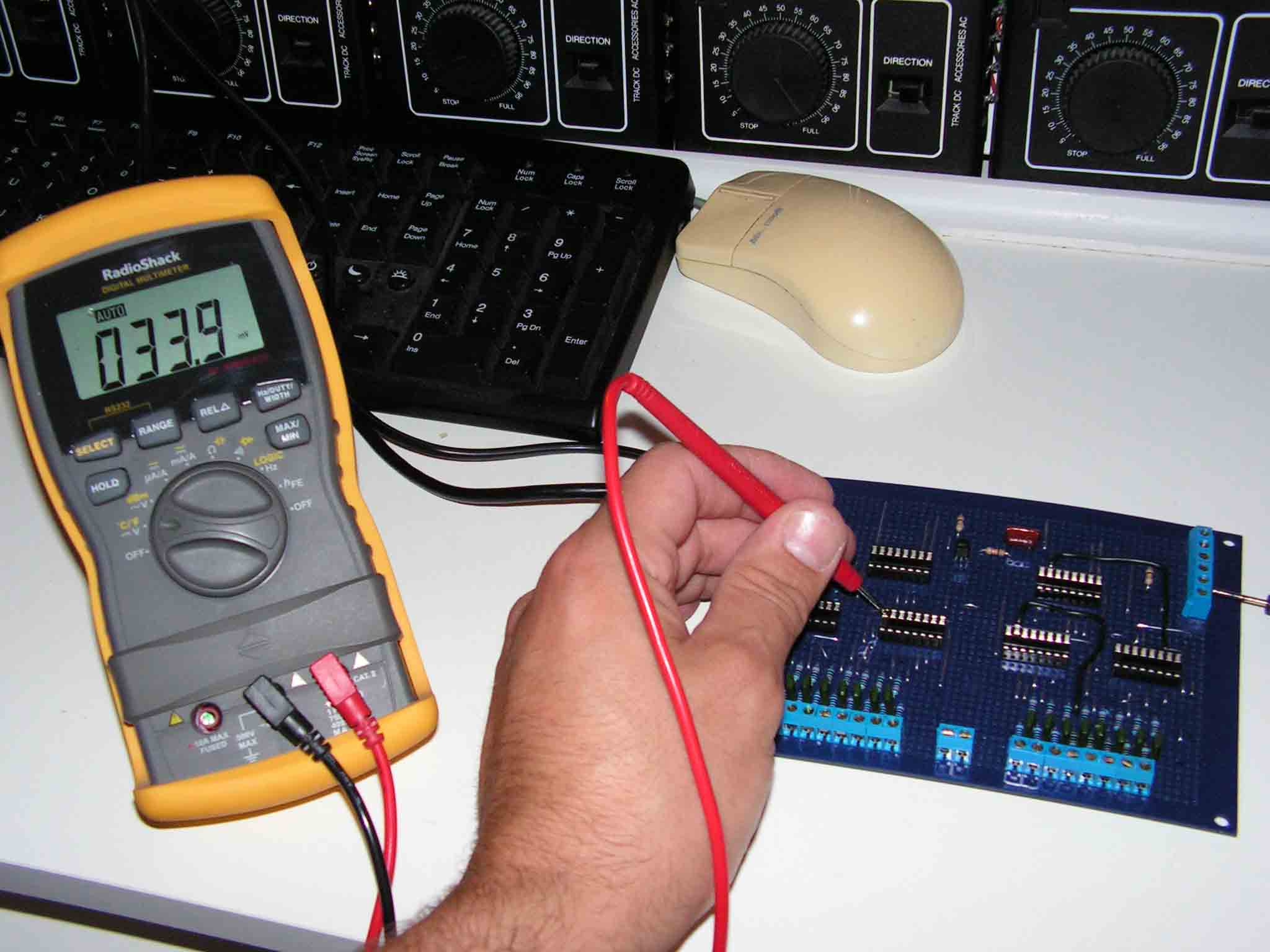
Testing the circuit boards before I insert the IC's.
Only one from the six circuit boards had a minor error. |
|
|
|
|

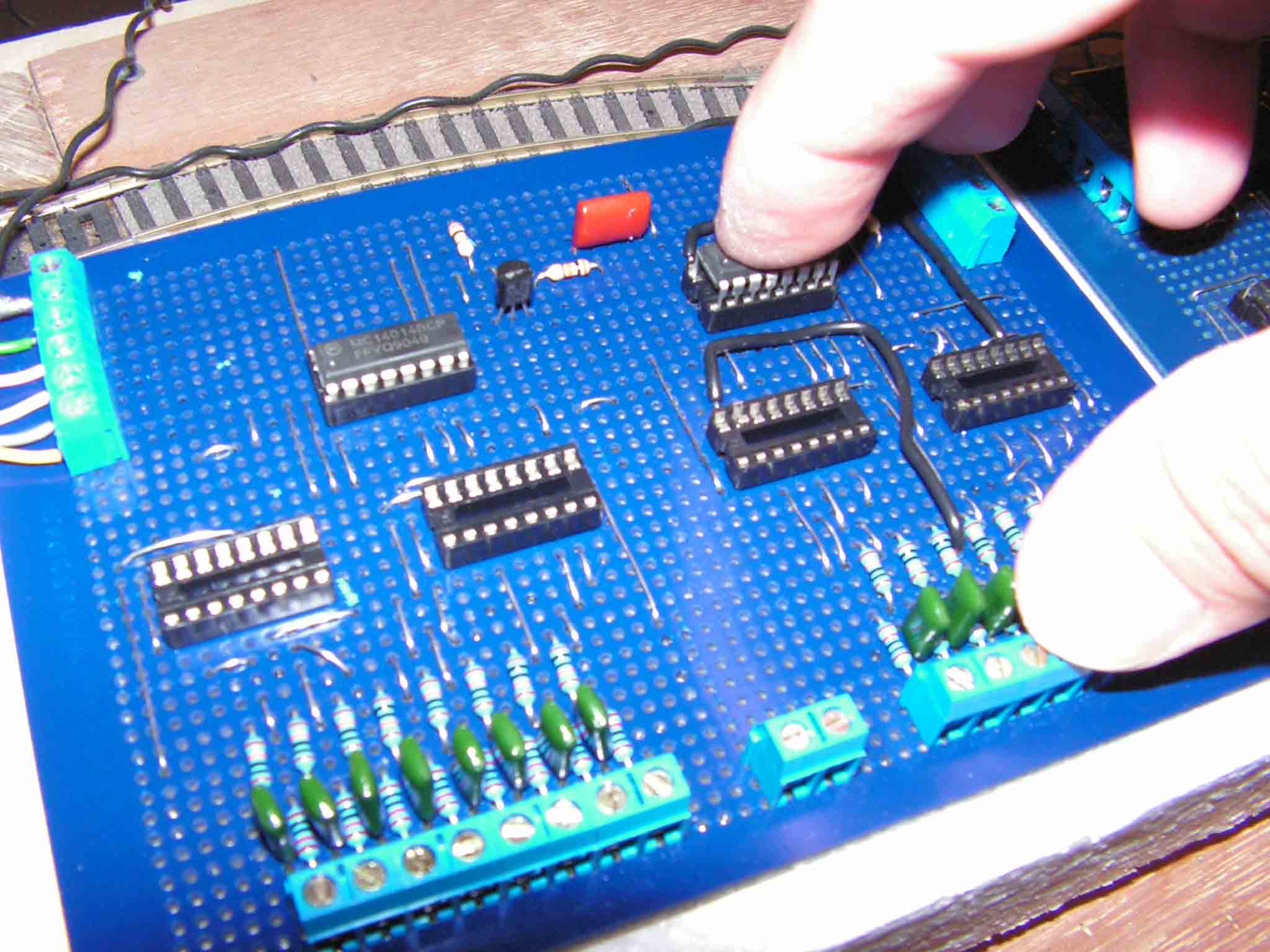
Once they pass the test the IC's get inserted. |
|

Connected to the computer, the inputs can be checked
for functionality. |
|
|
|
|

The monitor of the first computer. The S88 test
screen is used to test the circuit boards. |
|

The
interface which connects the S88 circuits to the printer port of the
computer. |
|
|
|
|
|
|
|
|
|
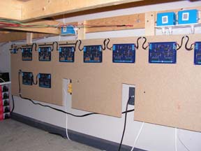
The S88 circuits chain linked together. The small
circuit at the beginning is the interface. All those circuit boards are
used for occupancy detection. At this time I have a total of 9 circuits
with 16 detectors each, so that totals 144 detectors. The computer is
capable of keeping track of 31 S88 circuits totaling 496 detectors! I
have plenty space for expansion, but at this time I am not in the mood
to solder another circuit board. |
|
|
|
|
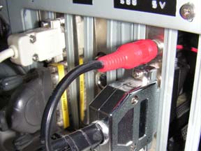
The occupancy detection signal from the train to the
computer. |
|
|
|
|

A section of track with detection. A car with a build
in resistor over the wheels will cause a flow of current to pass trough
the opto coupler from the detector. |
|
Elke kabel
is voorzien van een nummer welke overal, ook in de computer, het zelfde
is. |
|
|

De
digitale spanning van de secties welke detectie hebben, komen
binnen bij de bezetmelders. Het signaal gaat nu door naar de S88. |
|
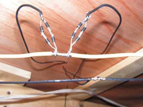
Diodes
zorgen voor een spanning val op het rails welke niet van detectie is
voorzien, om de digitale spanning gelijk te houden over de gehele
spoorbaan. |
|
|
|
|

Het
signaal van de bezetmelders komt binnen bij de S88 en gaat via de
interface naar de computer. |
|
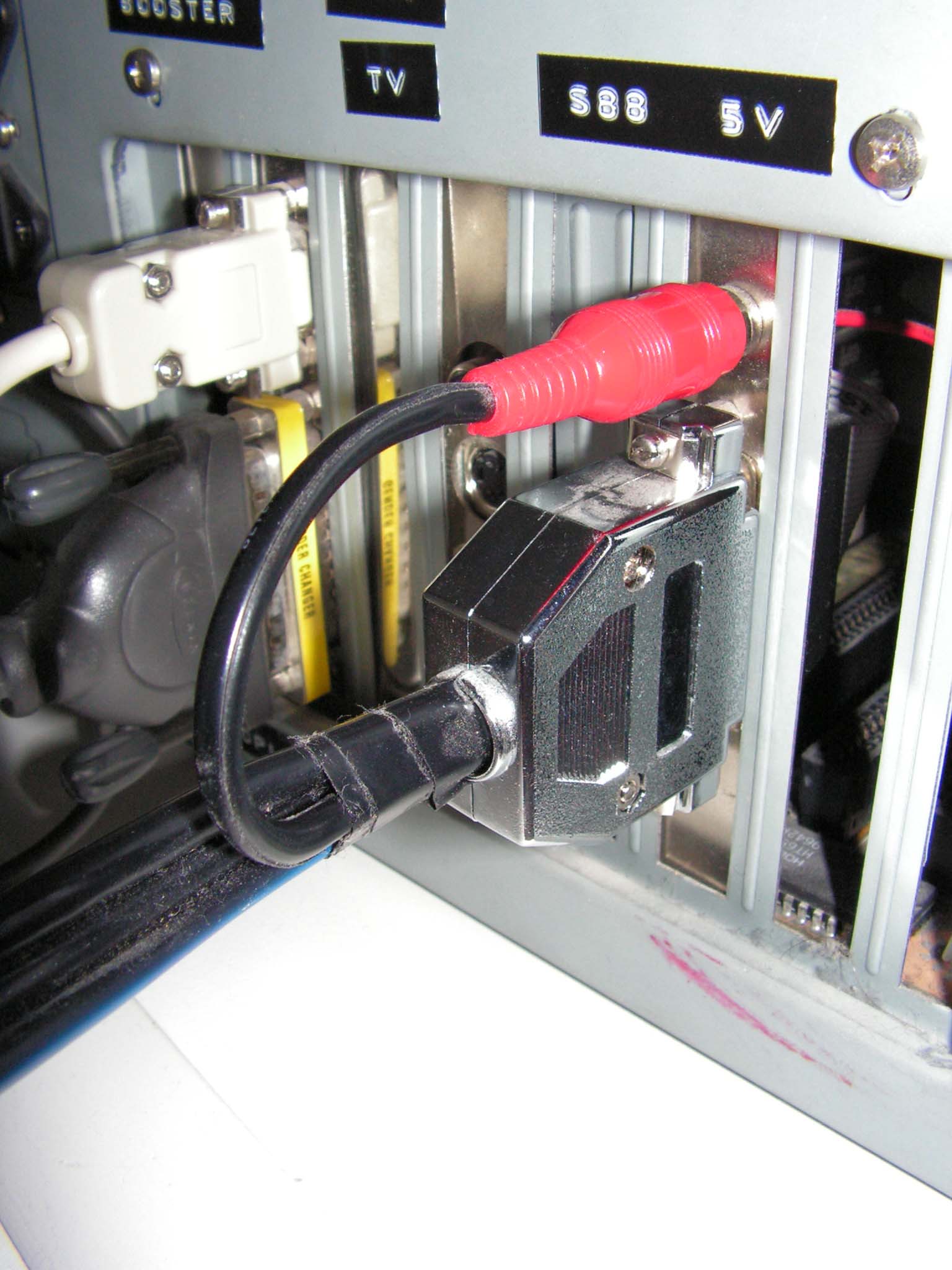
Uiteindelijk komt het bezet signaal binnen in de computer. De 5 volt,
welke nodig is voor de S88, komt direct uit de computer voeding. |
|
|
|
|
|
|
|
|
This is just a small part of the digital system. In
various articles I describe each individual piece to the puzzle.
Enjoy and try for yourself. You be convinced once you
discover the benefits of digital control system, whether dcc or
Motorola. |
This page is last updated on
15 July 2012
NLMS - Dutch ModelRailroad -
www.nlms.info